.svg)
For best results ensure that all Mounting, Sensor Placement, Wiring and Setup with Link ECU (if applicable) instructions are followed
Mounting
Use the mounting holes to secure Link CAN Lambda modules to flat surfaces. Try to keep the CAN Lambda module as far from the heat of the exhaust as possible.
Link CAN Lambda module maximum temperature is 100 °C (212 °F)
Sensor Placement
Only genuine Bosch LSU 4.9 Wideband Lambda sensors are compatible with Link CAN Lambda Modules
To prevent fluids such as condensation from collecting between the sensor housing and sensor element, Bosch recommends that LSU 4.9 sensors be mounted 10° or more above horizontal.
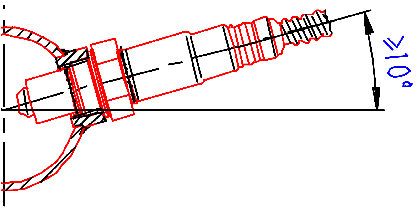
To avoid excessive heat the sensor should be mounted at least 1 meter from the engine exhaust port. Also ensure that the sensor is mounted greater than 1 meter away from the atmospheric end of the exhaust to ensure that readings are not contaminated by oxygen sucked up the exhaust. If the exhaust length is less than 2 meters then it is better to place the sensor closer to the engine
Wiring
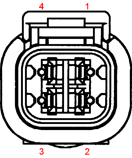
Power and Communication Connector Pinout
|
Pin |
Description |
|---|---|
|
1 |
Power |
|
2 |
GND |
|
3 |
CAN L |
|
4 |
CAN H |
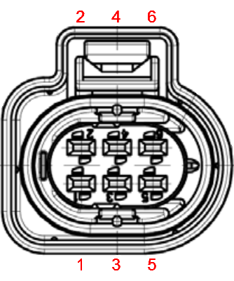
Sensor Connector Pinout
|
Pin |
Description |
|---|---|
|
1 |
APE |
|
2 |
IPE |
|
3 |
Heater |
|
4 |
Heater Power |
|
5 |
MES |
|
6 |
RE |
Connection Diagram
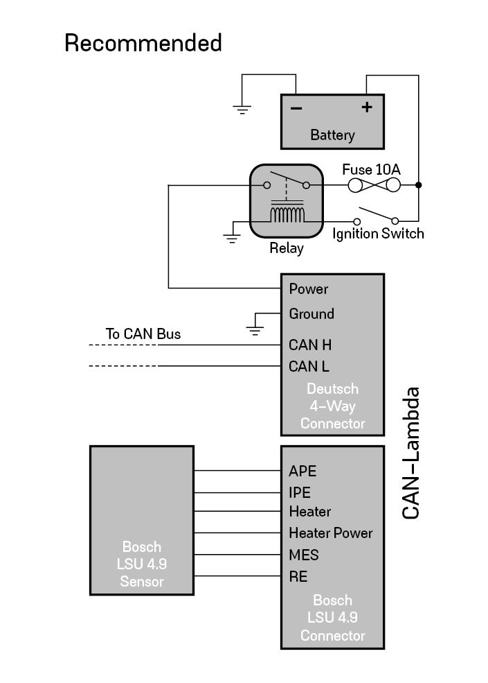
Alternative Connection Diagram
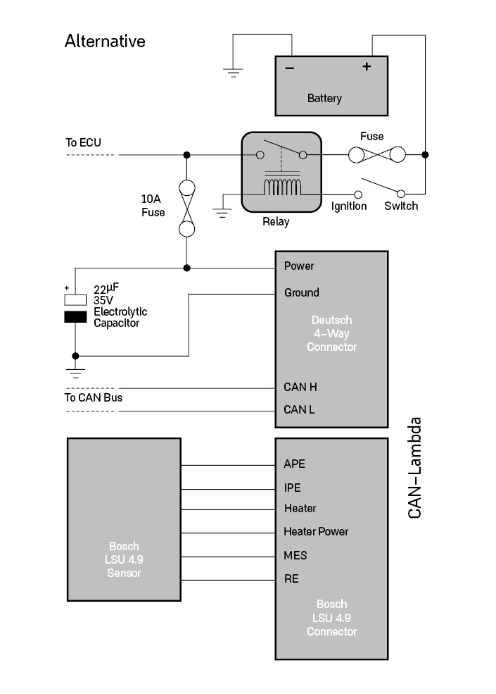
Setup with Link ECU
Link CAN Lambda modules allow up to eight wideband oxygen sensors to be measured, displayed and logged. A separate module is required for each oxygen sensor. The modules must be told which sensor they are connected to (eg cyl 1, cyl 2 etc...) so that they can be identified on the CAN bus. All Link CAN-Lambda modules are shipped preconfigured for a single installation. If only one sensor is being used the module requires no configuration
Programming Instruction
-
Navigate to ECU Controls > CAN Setup.
-
In the 'Mode' tab ensure the appropriate CAN Module is selected.
-
In the CAN Configuration box:
-
Set the mode to 'User Defined'.
-
Ensure the Bit Rate is set to '1 Mbit/s'
-
-
In the Data box:
-
Select a free channel and set its Mode to 'Link CAN-Lambda'.
-
In the CAN ID box, set the ID to 950, leave the format on 'Normal'.
-
-
Switch to the CAN Devices Tab.
-
Connect a Link CAN-Lambda module to the CAN Bus you selected in step 2.
-
Press the 'Find Devices' button.
-
One or more devices should appear in the list, if they do not go back to one and check your settings, check your CAN Bus and ensure that the device is receiving power.
-
Select the device you wish to change. All modules are shipped assigned to Lambda 1, this means you must attach the module you wish to use for Lambda 1 last.
-
Use the parameter column drop down box to reassign the device.
-
Use the bit rate column to change the devices bit rate.
-
Once you are satisfied with the changes, press the 'Send' button.
-
Cycle power to CAN Lambda Module only - not the ECU (unplug Deutsch connector for example) If you cannot cycle the power to the CAN Lambda Module without also cycling power to the ECU, press the Ok button to close CAN Setup before you cycle ECU power.
-
To add more modules repeat steps 6 to 13