.svg)
Link CAN-Lambda modules are configurable to allow use in a variety of applications and with different CAN Bus bit rates. From the factory, Link CAN-Lambda modules are all configured for:
-
Device identifier 0
-
1 Mbit/s bit rate
When using only a single Link CAN-Lambda module, no configuration of the module is required unless the default CAN bit rate of 1Mbit/s is not suitable.
Up to eight Link CAN-Lambda modules can be used on a CAN bus at any one time. As all Link CAN-Lambda modules are configured to device identifier 0 at the time of manufacture, if more than one module is to be used it/they will need to be configured to have a unique device identifier so it can be recognised on the CAN bus. Or if they are desired to be used on a different bit rate CAN bus (eg 500 kBps). When using Link CAN-Lambda modules with Link ECUs this is easily performed using PCLink. This uses the Link ECU as the communication bridge to connect the PC to the CAN bus through the ECU. When using multiple Link CAN-Lambda modules with other manufacturers ECUs or displays, this procedure must first be performed using PCLink and a Link ECU otherwise it can be done manually using a suitable CAN bus tool. Module Configuration is detailed further in following sections.
The receiving ECU or display must be configured using the CAN information supplied in the following sections. Some manufacturers may supply CAN template products for their devices that are pre-configured for use with Link CANLambda modules.
When using Link CAN-Lambda modules with Link ECUs on firmware greater than V5.6.0, the ECU can be easily configured in the ECUs CAN setup as described in the section on Setup with Link ECU. For use with other manufacturers ECUs and displays a custom CAN configuration will need to be set up using the information in the following sections.
CAN Bus Wiring
A CAN bus consists of a main bus (trunk) with devices individually joined to the bus. Each end of the bus must be terminated with a 120R resistor (1/4 Watt minimum). There is no CAN terminating resistor in the Link CAN-Lambda Module. The trunk (main bus) must be a total length of less than 15m. The two wires of the bus must be twisted together with a rate between 33 and 50 twists per meter. (20mm to 30mm between twists) Each device needs to be connected into the main bus. The length of the wire used to connect to the bus must be less than 200mm.
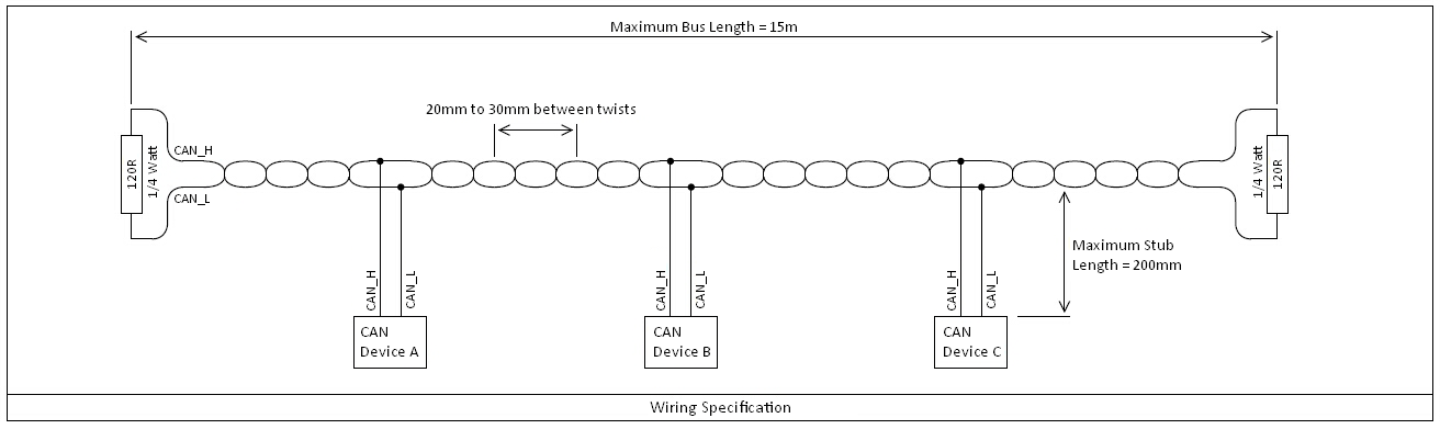
To simplify the installation, the following devices contain terminating resistors:
-
Link ECUs.
-
DisplayLink. Note that the terminating resister is in the connector of the displays power supply cable.
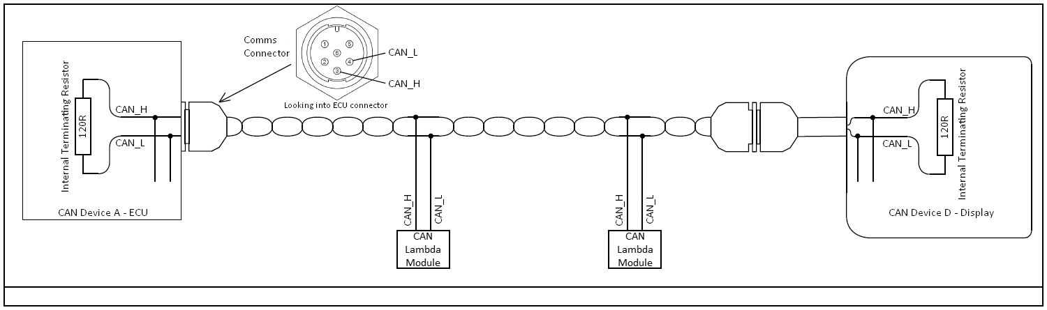
This means that these devices can only be used at the end of the bus. If you want to connect these devices to the middle of the bus, please contact your local Link distributor to arrange the removal of the internal resistor.
Example
The following is an example using devices to terminate the bus. Here Link CAN Lambda Modules have been added to the bus.
Transmitted Information
Link CAN-Lambda modules transmit the following information:
-
Lambda value
-
Sensor Temperature
-
Controller Error Codes
-
Controller Status
-
Pump Current
-
Battery Voltage
-
Heater Average Voltage
When connected to a Link ECU using the built in Link CAN-Lambda CAN communication mode, this information is displayed on the following parameters:
-
Device identifier 0 (default)
-
Lambda 1
-
Lambda 1 Temperature
-
Lambda 1 Status
-
Lambda 1 Error
-
-
Device identifier 1
-
Lambda 2
-
Lambda 2 Temperature
-
Lambda 2 Status
-
Lambda 2 Error
-
-
Device identifier 2
-
Lambda 3
-
-
Device identifier 3
-
Lambda 4
-
-
Device identifier 4
-
Lambda 5
-
-
Device identifier 5
-
Lambda 6
-
-
Device identifier 6
-
Lambda 7
-
-
Device identifier 7
-
Lambda 8
-
Information is transmitted on CAN Id 950 + device identifier. Eg device identifier 4 transmits on CAN Id 954. Transmission uses a compound message format (or sometimes called filter byte) with the frame index in Data 0
|
CAN Id 950 (0x3B6) + device identifier |
|||||||
|---|---|---|---|---|---|---|---|
|
Data 0 |
Data 1 |
Data 2 |
Data 3 |
Data 4 |
Data 5 |
Data 6 |
Data 7 |
|
50 |
Error Code |
Lambda
|
Lambda
|
Sensor Temperature (High Byte) |
Sensor Temperature (Low Byte) |
Status |
- |
|
- |
See section on error codes |
x1000 Lambda
|
deg C (eg 780 = 780 deg C) |
0 = Off
|
- |
||
|
51 |
- |
Pump Current
|
Pump Current
|
Battery
|
Battery
|
Heater Voltage
|
Heater Voltage
|
|
- |
- |
x1000 mA (eg 1234 = 1.234 mA) |
x100 V (eg 1370 = 13.70 V) |
x100 V (eg 1370 = 13.70 V) |
|||
Received Information
Optionally information can be transmitted to the Link CAN-Lambda module. This allows the module to turn off the sensor heater when the engine is not running and perform exhaust pressure compensation.
The built in Link ECU Link CAN-Lambda CAN communication mode automatically sends this information if it is available to all modules.
The Link CAN-Lambda module will wait for two seconds after power up to see if this information is received. If it is not, sensor control will be enabled. IF the information is received, sensor control will not be enabled until engine RPM goes above 400 RPM and disable sensor control when engine speed falls below 10 RPM.
All modules receive this information on the same CAN Id 958 (0x3BE).
|
CAN ID 958 (0x3BE) |
|||||||
|---|---|---|---|---|---|---|---|
|
Data 0 |
Data 1 |
Data 2 |
Data 3 |
Data 4 |
Data 5 |
Data 6 |
Data 7 |
|
85 |
- |
Engine Speed (High Byte) |
Engine Speed (Low Byte) |
Exhaust Absolute Pressure (High Byte) |
Exhaust Absolute Pressure (Low Byte) |
Use Exhaust Pressure |
- |
|
- |
- |
RPM (eg 3000 = 3000 RPM |
x10 kPa (eg 1100 = 110.0 kPa |
0 for no correction |
- |
||
Pressure compensation range is 50-250 kPa. Absolute pressure must be used not gauge pressure (ie 0 = absolute vacuum). If a correct pressure value is not sent to the Link CAN-Lambda module Data 6 must be zero to ensure pressure correction is not used.
Manual Module Configuration
Link CAN-Lambda modules can be manually configured with the following information:
-
CAN Bus Bit Rate (1 MBps default)
-
Device identifier (0 by default)
Where it is not practical to use a Link ECU and PCLink to configure the Link CAN-Lambda module, it may be configured using a suitable CAN bus analyser tool, or any CAN device that allows transmission of data in the format shown below (eg dash display).
Finding a Link CAN-Lambda Modules Current Device Identifier
To program a module, it must be connected to a CAN bus running at the same bit rate as the module is currently configured. The first step is to determine what device identifier the Link CAN-Lambda module currently uses. This can be performed by finding the CAN Id that it is currently sending its transmit data on. The device identifier currently used is this CAN Id - 950. So, if the Link CAN-Lambda module is currently transmitting data on Id 951, then its device identifier is 1 (951 - 950 = 1). The reason we need to know the current device identifier is so we can address our programming command directly to that device.
Programming a New Device Identifier and Bit Rate
To program a new configuration the following information must be sent to the Link CAN-Lambda module. It is OK to send the same information multiple times. Changes will not be applied until next time power is cycled to the Link CAN-Lambda module
Send on CAN Id 958 + device identifier (eg send on 959 if current device identifier is 1).
|
Data 0 |
Data 1 |
Data 2 |
Data 3 |
Data 4 |
Data 5 |
Data 6 |
Data 7 |
|---|---|---|---|---|---|---|---|
|
24 |
New device Identifier |
New bus frequency |
- |
- |
- |
- |
- |
|
- |
New identifier between 0 and 7 inclusive |
0 = 100 kbit/s
|
- |
- |
- |
- |
- |
Program OK Reply
If the program command is accepted the following reply will be sent on CAN Id 950 + old device identifier (eg if device identifier was 1 before program command, reply will be on CAN Id 951).
|
Data 0 |
Data 1 |
Data 2 |
Data 3 |
Data 4 |
Data 5 |
Data 6 |
Data 7 |
|---|---|---|---|---|---|---|---|
|
24 |
New device identifier OK |
New bus frequency OK |
- |
- |
- |
- |
- |
|
- |
0 = OK
|
0 = OK
|
- |
- |
- |
- |
- |