

Link has over 30 plugin ECUs, the intention of this line is to allow easy installation into an existing wiring harness. The way we interface with a factory wiring harness is surprisingly modular, shown in this article is a Mitsubishi EVO8, but all of our plugins follow roughly the same form.
The Top Board
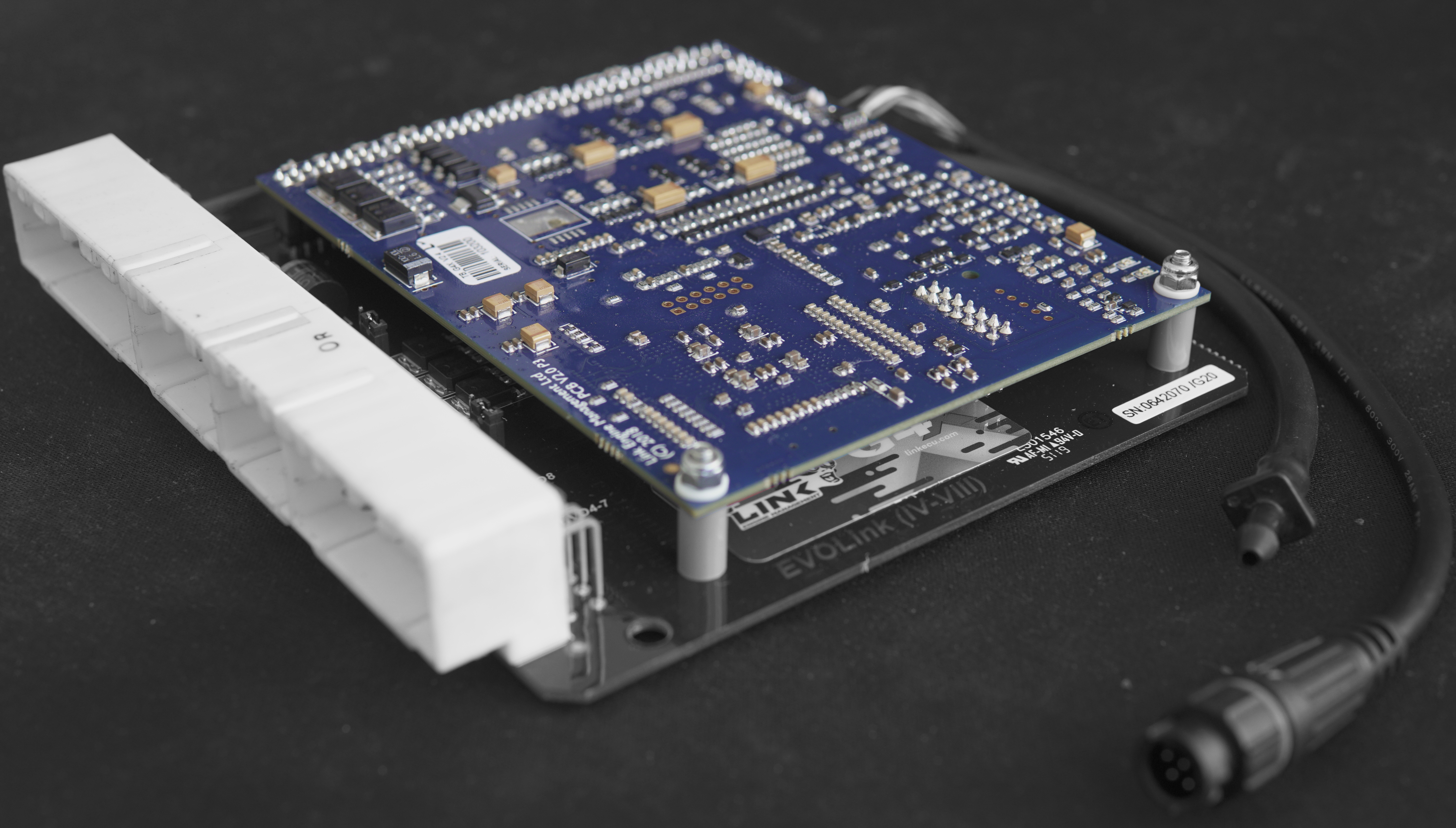
This is the ECU part of the plugin, it handles all of the inputs, outputs, USB, CAN, timing, fuel and ignition calculations to make your car run. All plugins have a top board, the ECU serial number is tied to this part of the plugin.
The Bottom Board
Everything that isn't the top board.
Main Header
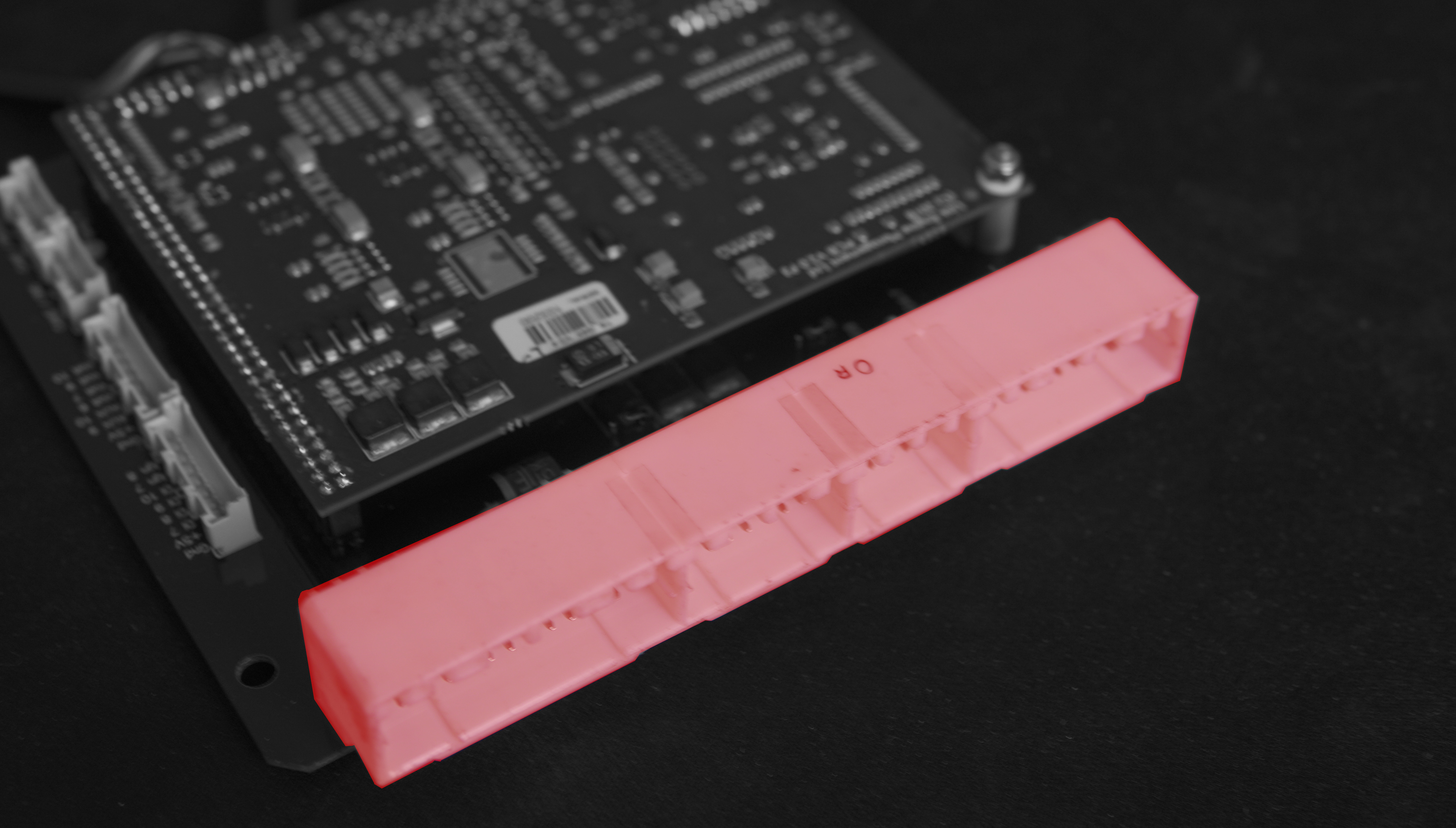
This is where the factory wiring harness connects to the ECU.
CAN and XS Plugs

Shown here are the CAN and XS Loom locations. Most ECUs have two CAN bus plugs, but some have only one where CAN 2 is needed for OEM CAN bus integration.
The XS Loom plugs have the functions associated with the pin location printed next to them. Not all ECUs have an XS Loom, and not all ECUs have the same availability of pins on the XS Loom.
Jumpers
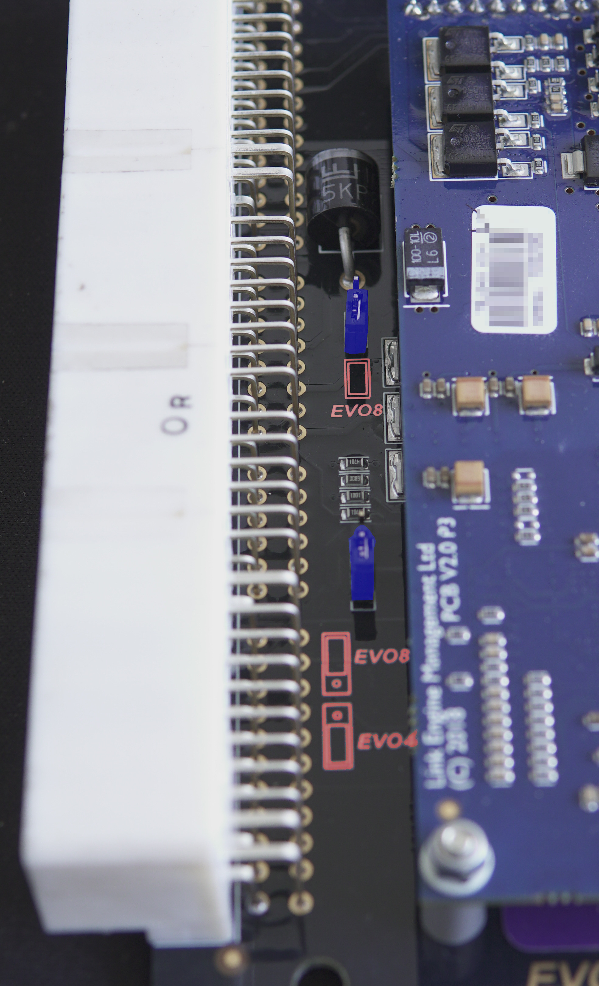 |
Some plugin ECUs have jumper or switch settings on the bottom board you must check and set before the engine will run properly. Here the jumpers are highlighted in blue and the silkscreen shows the options in red. See your manual for details.
Note in this picture you can also see some of the supporting electronics which interface the factory wiring loom requirements for power, ground, pull up and pull down resistors to our top board. |
USB
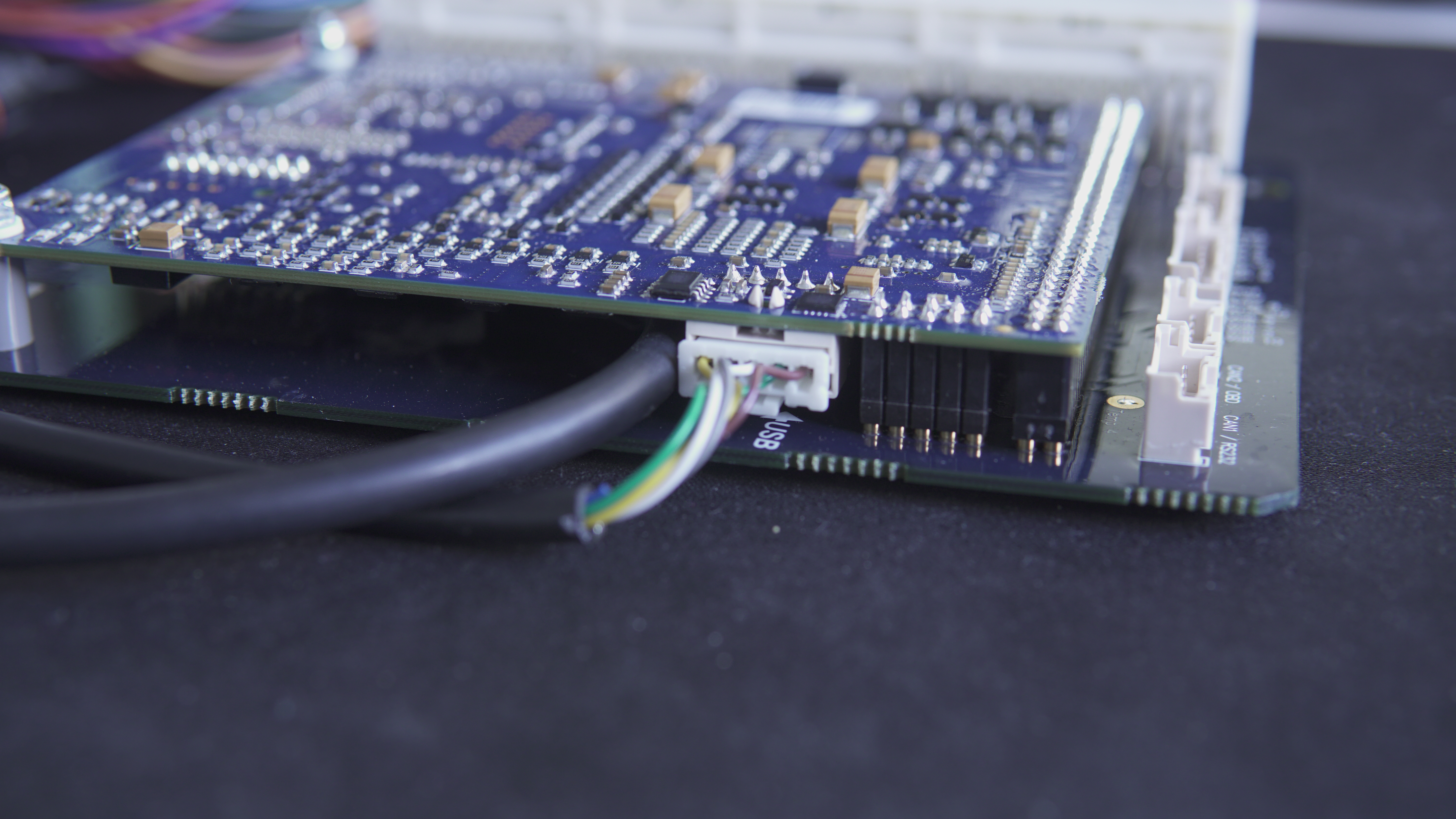
The USB cable does not attach to the bottom board.
DO NOT ATTACH YOUR USB CABLE TO EITHER CAN PLUG, IT MAY CAUSE DAMAGE TO YOUR COMPUTER.
The USB location is noted on the bottom board, but the plug is on the bottom side of the top board.
In this picture, you can also see the MAP sensor hose.
Link Plugin ECU's are based on the highly capable G4X XtremeX ECU, for a specifications list click here.
Comments
0 comments
Article is closed for comments.